Advanced Settings
Advanced settings are accessed by clicking on
the 'Brain button', a feature well-known to users of the original PHD.
PHD2 has a considerably larger set of parameters that can be
adjusted to optimize your guiding performance. Although these
are
called "advanced" settings, they are not particularly difficult to
understand, and you shouldn't hesitate to explore them. All
of
the fields on these forms include "tool tips", small message windows
that describe each field in some detail. Simply
"hover" the
cursor over the field to see the tool-tip. In many cases,
this
will provide all the information you need. Because there are
many more settings available, the Advanced Dialog in PHD2 is organized
into tabs, and the documentation will follow that model as well.
Global Tab
Guiding Tab
Camera Tab
Mount Tab
AO Tab
Global Tab
Most of the fields on the global tab deal with overall program
functions and behavior. Several of them deal with
logging and debugging functions, which
will be discussed first.
Logging and Debug Output
PHD2
can optionally produce two types of log files: a debug log and a
guiding log. Both are highly useful for different reasons.
The guiding log is similar to the one produced by PHD, but
with
extended information. The guide log is intentionally formatted to
allow easy interpretation by either a human reader or an external
application. For example, the PHDLab application (not
part of the PHD2 project) can produce a variety of graphs and summary
statistics based on data in the PHD2 guide log. But the log can also be easily imported into
Excel or other applications for analysis and graphing.
When importing into Excel, just specify that a comma should be used as a
column separator The
debug log
has a complete record of everything that was done in the PHD2
session, so it is very helpful in isolating any problems
you have. It also employs a human-friendly (albeit verbose)
text format, so it's
not
difficult to examine the debug log to see what happened. If
you
need to report a problem with the software, you will almost certainly
be asked to provide the debug log file. If you have neither log
file available, you are unlikely to get any help.
These two log files
will be generated if 'Enable Logging' is checked on the
Global
tab. The location for the files is controlled by the 'Log
File
Location' field further down in the dialog. By default, log
files
are stored in the OS-specific default directory for application data files.
In Windows7, for example, the files will be stored in a 'PHD2'
sub-folder in the "AppData\Local" location. This may not be a
convenient location, so you can specify a different folder using this
edit field.
In some unusual cases, you may need to capture guide
camera images, usually to support debugging and problem resolution.
This can be enabled by checking the 'Enable Star-image
Logging'
checkbox.
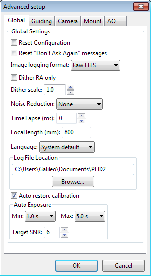
General Parameters
The remaining controls on the
'Global' tab are well-described by their respective tool-tips, but they
are summarized here for completeness:
- 'Reset Configuration' - restores all settings to their
initial values as if PHD2 had been freshly installed
- 'Image format' - specifies the file format if
star-image logging is enabled
- 'Dither
RA only' - for companion apps that use the PHD2 server interface,
specifies that dithering should be done only on the RA axis
- 'Dither scale' - controls the magnitude of the dithering
operation
- 'Noise
reduction' - specifies the algorithm to use for handling noisy guide
camera images - those for which dark frames are not sufficient.
Choices include None, 2x2 mean, and 3x3 median. Both 2x2 mean
and 3x3
median will reduce the noise considerably. 3x3 median is especially
effective at removing hot pixels and neither will significantly affect
guiding accuracy. However, creating a bad-pixel map is
likely to be a better solution with less impact on your ability to
detect faint stars.
- 'Time lapse' - imposes a fixed delay between
guide exposures. This can be useful if the guide exposures
are
very short and you don't want to overload either the mount or the
camera
link with very high traffic rates.
- 'Focal length' - the focal length of the guide scope (millimeters). This provides one of
two parameters needed by PHD2 to compute the image scale and thus
report guiding performance in units of arc-seconds. The other
parameter required for this is the guide camera pixel size, located on the
'Camera' tab.
- 'Language' - determines the language
used in the PHD2 user interface, subject to available localization.
Changing this will usually require a program restart
- 'Auto restore calibration' - tells
PHD2 to automatically reload the most recent calibration data as soon
as the equipment is connected. Be sure to read the 'Auto
calibration' section of the help file to understand the implications
and potential risks of doing this.
- 'Auto Exposure' - these are the settings that control Auto exposure time.
- Min Exposure - the minimum exposure time. PHD2 will not set the exposure time
less than this value, even if the guide star SNR is higher than the target SNR value.
If the min exposure time is set too low, you could end up sending excessive small
corrections to the mount which may not give the best guiding results. Users with AO
units would want to set this to a lower value, since rapid small corrections are often
desirable with an AO.
- Max Exposure - the maximum exposure time. Before a guide star is selected, PHD2
will set the exposure time to the maximum value. Once a guide star is selected, PHD2
will then incrementally decrease the exposure time until the desired SNR is reached.
- Target SNR - this is the average SNR value that PHD2 will attempt to achieve
by adjusting the exposure time. SNR can fluctuate from frame to frame even with a
fixed exposure duration, so be sure to account for that when choosing a target SNR
value. PHD2 will reject frames when SNR drops below 3.0. The default value of 6.0
should provide enough of a cushion to prevent fluctuations from causing the SNR to
go below 3.0.
Guiding Tab
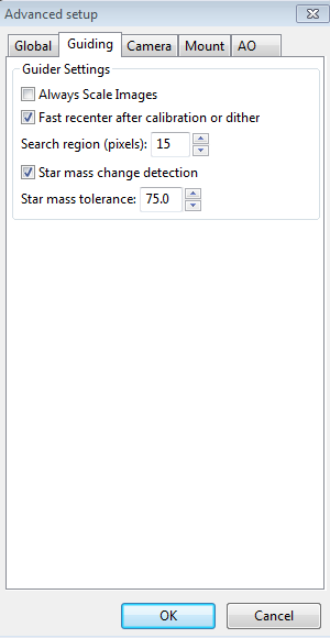
There are relatively few parameters found on the 'Guiding' tab.
Their use is as follows:
- 'Always
Scale Images' - tells PHD2 to always rescale the guider image to fit
the display window. PHD2 does this automatically in almost
all
cases, so you'll rarely need to do this.
- 'Fast
re-center after calibration or dither' - during calibration or
dithering, the mount may be moved a significant distance from the
initial "lock" position. If you click this checkbox, PHD2 will
move the mount back to the lock position as quickly as possible,
using the largest guide commands permitted by the 'Max Duration' settings of
your guide algorithms. This is only an optimization, so the use
of this checkbox is completely optional.
- 'Search
region' - specifies the size of the "tracking rectangle", in units of
pixels. You may need to increase this value if your mount
does
not perform well or, more commonly, if it's not well-aligned on the
celestial
pole.
- 'Star mass change detection' - tells PHD2 to monitor the
brightness and size of the guide star compared to the sky background.
- 'Star mass tolerance' - if 'star mass change detection'
is checked, PHD2 will trigger a 'lost star' error if the measured
brightness and size vary by more than this percentage. This
might be useful if you have two stars inside the tracking rectangle and
you want to be sure that PHD2
doesn't mistakenly "switch stars."
It can also
prevent errors caused by thin clouds, high camera noise, or alpha
particle "hits";
but it may be unreliable if you are guiding on a faint star. If
you are getting too many 'lost star' errors when the star is plainly
visible on the display, try increasing the value of this setting.
Setting the value to 100 effectively disables the warnings
entirely.
Camera Tab
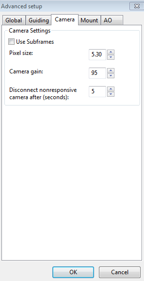
The controls on the 'Camera' tab are used as follows:
- 'Use subframes' - For cameras that support this
feature, PHD2
will download only a subframe of each guide
exposure. This is very useful for cameras with slow download times
and can mean the difference between the camera being too slow
to effectively guide and being quite responsive. When this feature is
enabled,
only a small subframe (100x100 pixels) will be downloaded once a star
is selected. This feature applies to both calibration and guiding.
During initial looping without a selected star, the full
frame is downloaded, but once a star is selected, only this small
subframe is downloaded. If you are using subframes but want to
see the full frame to select a different star, just click anywhere
outside the subframe.
- 'Pixel
size' - The guide camera pixel size in microns. This is the second of two parameters needed by PHD2 to compute the
guider image scale and thus report guider statistics in units of
arc-seconds. Refer to your camera documentation to determine
the
correct value.
- 'Camera gain' - Sets the gain level for the many cameras
that support this feature. If
you really want to use a bright star and a longer exposure duration or
if your camera makes a very noisy image, try reducing this parameter.
- 'Disconnect
nonresponsive camera after (seconds) - Camera malfunctions will
sometimes occur, often because of faulty USB connections. In many
cases, the camera will not return the requested image data, and PHD2
will appear to "hang." This parameter determines
how long PHD2 should wait for a response after the expected exposure
time has expired. For example, a timeout value of 5 seconds in
conjunction with an exposure time of 2 seconds will tell PHD2 to wait
up to 7 seconds for a response. If the data are not received
within that period, PHD2 will attempt to halt the operation, disconnect
the camera, and display an alert message in the main window.
Since a hardware problem is likely the underlying issue, this
recovery attempt won't always succeed. It is advisable to be
"generous" with these timeout values to avoid spurious recovery
actions. Also, if you are using a guide camera that shares
electronics with the main imaging camera, you should set this timeout
to a large
value, well above the maximum expected time for a full-frame download
from the main imager. At this time, this affects users of
the SBIG driver that is packaged with Sequence Generator Pro.
Regardless of whether PHD2 is able to handle the situation
gracefully, the underlying problem is almost certainly in the
hardware or the camera driver and will need to be resolved before
guiding is continued.
Mount Tab
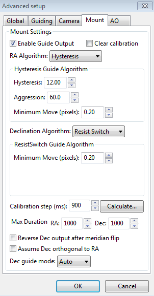
The
mount tab is the most complex area of Advanced Settings largely because
it has so many parameters and UI controls. Most of these
settings
are closely tied to the various guiding algorithms, and the
contents of the dialog will change significantly if you
change the algorithm selections. For that reason, all the
parameters related to guide algorithms will be treated together, in a
separate section.
The remaining controls, the ones that are independent of the guiding
algorithm selections, are described below.
- 'Clear calibration'
- tells PHD2
you want to clear the calibration data currently being used and
re-calibrate
before
guiding is restarted. You might do this for a variety of
reasons
- you might have moved the guide camera, you might have done a meridian
flip and want to recalibrate on the "new" side of the pier, etc.
You can also accomplish the same result by doing a Shift-Click on
the guiding icon on the main page, which will force a re-calibration.
- 'Enable
guide output'
- this is normally checked because it tells PHD2 to send guide
commands to the mount. But there are some
circumstances
where you might want to disable this, usually because you want to
observe the uncorrected behavior of the mount. For example,
you
can disable guider output in order to see the general shape and
amplitude of your mount's periodic error or to check the amount of
drift from polar mis-alignment.
- 'Calibration
step-size' - specifes the duration of the guide pulse that
PHD2
will use during calibration. Its use is described in the
'Auto
Calibration' section of the 'Basic Use' help page. You can
adjust
the value depending on whether the guide star is moving "too quickly"
or
"too slowly" during calibration. As a general guideline, it
is
good to calibrate within about 30 degrees of the celestial equator
(declination = 0), and to use a calibration step size that will result
in 8-14 "steps" in each direction. The 'calculate...' button
to
the right of this control will launch a dialog that can help you
compute an appropriate value:
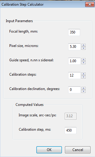
To
use the calculator,
be sure the topmost three edit controls are
correctly filled in. If you have already specified the focal
length and
the camera pixel size in the 'Global' and 'Camera' tabs respectively,
those fields will already be populated in this form. If you are
using an ASCOM connection to your mount, the fields for "Guide speed"
and "Calibration declination" will also have the correct values.
Otherwise, you'll need to supply them yourself. The guide
speed is specified as a multiple of sidereal speed - most mounts will
use something
like
1X or 0.5X sidereal, but you can choose something else. You
can
leave the 'calibration steps' field at the default value of 12, which
is likely to result in a good calibration. Use of a significantly
smaller value raises the likelihood that seeing errors or small mount
errors will cause calibration errors . As you change the values
in these fields, PHD2
will recalculate your current image scale and a recommended value for the
calibration step-size. If you then click on 'Ok', that value
will
be inserted into the calibration step-size field of the 'Mount' dialog.
Clicking 'Ok' will also populate the focal length and camera
pixel size fields in the 'Global' and 'Camera' tabs, so any changes you
made in the calculator will be reflected there as well. However,
this will not be done if you click on 'Cancel' in the calculator
dialog.
- 'Max Duration RA' - specifies the maximum allowed
guide pulse duration for right ascension. You might reduce
this
below the default value if you want to avoid "chasing" a large
deflection that could be caused by a spurious event (e.g. a sudden 'hot
pixel') .
- "Max Duration Declination' - specifies the
maximum allowed guide pulse duration for declination (same as above but
for declination). This can be useful to avoid
"over-correction" and subsequent direction reversal in declination
guiding.
- 'Reverse Dec
output after meridian flip' - tells PHD2 how to adjust the
calibration data when you use the function to "flip" it. Some
mounts track their 'side of pier' state and automatically reverse the
direction of guide commands in declination. Others, perhaps
most
mounts, do not do this. In either case, PHD2 needs to know if
the
mount will automatically change its behavior based on
side-of-pier. You may have difficulty finding information about
how your mount behaves in this respect, so it's probably easiest to
just run a quick experiment. With the checkbox disabled,
calibrate on one side of the pier, then move the mount to the other
side. Select 'Flip Calibration' under the 'Tools' menu, and
start guiding. If the guiding works normally, leave the box
un-checked; but if you see run-away in declination, check the box and
repeat the experiment.
- 'Assume
Dec orthogonal to RA' - Normally, the calibration process independently
computes the camera angles for both right ascension and declination.
There is no need for great precision on these values, and the
default behavior normally works well. However, if your mount has
very high periodic error or you are dealing with very bad seeing
conditions, you may want to force the RA and Declination angles to be
perpendicular. If you choose that option, PHD2 will compute the
camera angle for RA, then assert a declination angle that is orthogonal
to it.
All of the other controls in this dialog are related to the guiding
algorithms you have chosen and are described here: Guiding Algorithms and Settings
AO Tab
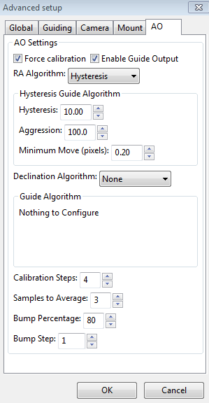
Most
of the edit controls at the top of the AO tab have the same meaning as
their counterparts on the 'Mount' tab. The guiding algorithms
apply to the control of the tip/tilt optical element in the AO device
itself, not to the "bump" commands sent to the mount. Since the
AO device is not trying to move a heavy piece of equipment, you can
afford to be more aggressive in your guide algorithm parameters.
If you use a hysteresis-based algorithm, for example, you should
probably start with a high level of aggressiveness, perhaps 100%.
Or you can choose the 'None' algorithm, which means there will be
no damping or history-based algorithm applied at all. In that
case, each correction will be based only on the most recent guide frame
and will make a 100% correction of the most recent deflection.
You
can use the four parameters at the bottom of the AO tab to control the
calibration process and the manner in which 'bump' operations are done.
The 'calibration step' field tells PHD2 the amount to move the
tip/tilt element in each of the up/down/left/right directions, in
units of AO steps, during calibration. The guide star position is measured at the
beginning and end of each "leg" of the calibration, and the 'samples to
average' parameter tells PHD2
how many samples to take at each of these
points. Averaging images is important because the seeing will
always cause the guide star to "bounce around" a bit. As
discussed earlier, the AO unit can make corrections
only within a limited range of guide star movement. You
will want to initiate mount 'bump' corrections before these limits
are actually reached, and the 'bump percentage' field is used for that
purpose. To move the mount, the full bump correction is
accomplished in steps - the 'bump step' field controls the size of
these increments. If the bump operation has begun and the guide
star remains outside the "bump percentage" area, PHD2
will increase the
bump size until the guide star is back within that range.
Additional movement from that point to the "center" position will
continue at the specified "bump step size". This complexity is
required in order to maintain good guiding, with no elongated stars,
even as the mount is being bumped. During the bump operation, the
AO is continuing to make corrections, so the long "mount bump" is
continuously offset by adjustments in the AO.