Tools and Utilities
Manual Guide
Auto-Select Star
Calibration Data
PHD2 Server
Drift Alignment
Lock Positions
Comet Tracking
Equipment Profiles
Simulator Parameters
Manual Guide
If you are connecting to a new mount and are encountering calibration
problems, you will probably want to be sure that PHD2's
commands are
actually getting to the mount. Or you may want to nudge the mount or
experiment with manual dithering. In the 'Tools' menu, click on
'Manual
Guide' and
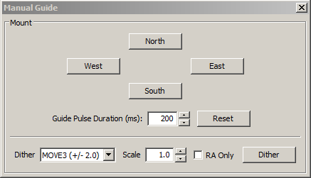
a dialog will appear to let you move the mount at guide speed in any
direction. Each time you press the button, a pulse of the duration
specified in the 'Guide Pulse Duration' field will
be sent. The default value is the 'calibration step-sze' set in
the Advanced Options dialog. If you are debugging calibration
problems, listen to (rather than watch) your mount to determine if the
mount is getting
the commands from PHD2. The idea here is just to figure out if the
mount is responding
to PHD2's
signals. You won't be able to see the mount move (it's moving
at guide speed)
but you may be able to hear it. Other options include watching the
motors themselves or
attaching a laser pointer to your scope and aiming it at something
fairly far away (to amplify your motions). If you have an
adaptive optics device attached, you'll see separate move buttons for
both the AO and the secondary mount.
Dithering
is used primarily with image capture or automation applications,
usually through the PHD2 server interface. However, you can do
manual dithering or experiment with dither settings using the controls
at the bottom of the dialog. The 'dither' amount field at the
left controls the amount the mount will be moved , in units of
pixels. You can scale this amount - i.e. multiply it by a
constant - by using the 'scale' spin control to the right. These
two controls establish a maximum amount of movement that will be used
for dithering - the product of 'scale' X 'dither'. When you click
on the 'Dither' button, PHD2 will move the mount by a random amount
that is less than or equal to the limit you have set, in one of the
north/south/east/west directions. The 'RA Only' checkbox will
constrain the dither adjustments to only east or west. Obviously,
if you are doing a manual dither in this way, you'll want to be sure
your imaging camera is not in the middle of an exposure.
Auto-Select Star
Clicking on 'Auto-select Star' under the 'Tools' menu, or using the keyboard
shortcut of <Alt>S, tells PHD2 to scan the current guide image
and identify a star suitable for guiding. PHD2 will try to select a star of sufficient brightness that is not
near another star and not too close to the edge of the frame. The
selected star may appear overly dim on the screen, but this is usually
not a problem. You can use the Star Profile tool
to examine the properties of the selected star - it should be
non-saturated with a sharp profile, the same properties you should look
for when choosing a guide star manually. The auto-select process is not
infallible, so you may need to select a star yourself if you don't like
the automated result. If you want to use Auto-Select, you should
definitely use either a bad-pixel map or dark library to reduce the
likelihood of PHD2 mistakenly choosing a hot pixel.
Manual Control of Calibration Data
Calibration data is saved automatically each time a calibration sequence completes
successfully. The use of the calibration data has been described
elsewhere (Using PHD Guiding),
including options for restoring calibration data from an earlier
time or "flipping" it after a meridian flip. You access these
functions using the 'Calibration' sub-menu under the 'Tools' menu. Two other
calibration-related items are shown there, namely the options to
clear the current data or to enter calibration data manually. The
"clear" option accomplishes the same thing as the 'Clear calibration'
checkbox in the Advanced Dialog - it will force a recalibration
whenever guiding is resumed. The 'Enter calibration data'
option should be used only under
very unusual circumstances and only if you're sure you know what you're
doing; but it is available as a matter of completeness. If you
click on the 'Enter calibration data' item, you'll see a dialog box
that allows input of relatively low-level calibration data. This
data might come from a much earlier session, perhaps extracted from the
PHD2 guiding log file.
PHD2 Server
PHD2 supports third-party imaging and automation applications that need to control the guiding process. Stark Labs' Nebulosity program
was the first to do this, but other applications have subsequently been
produced. By using the PHD2 server process, image capture
programs can control dithering between exposures or suspend guide
exposures while the primary imaging camera is downloading data.
To use these capabilities with a compatible application, you
should click on the 'Enable Server' option under the 'Tools'
menu. The server interface has been reworked substantially in
PHD2, and it's now possible
for an application to control most aspects of PHD2's guiding operations. Documentation for the
server API is available on
the PHD2
Wiki.
Drift Align
Drift alignment is a well-known technique for achieving polar alignment and
is considered by many to be the "gold standard". The Drift
Alignment tool is a "wizard-like" sequence of dialogs that can help
you work through the drift alignment process and get quantifiable
results. Once you've calibrated your guider, click on 'Drift
Align' under the 'Tools' menu. The first Drift Align dialog will
appear to help you adjust the azimuth on your mount. If you are
using an ASCOM mount, you'll have the option of slewing to an area
near the celestial equator and the celestial meridian. If you're
not using an ASCOM mount, you'll need to slew to that location
manually. Once the scope is positioned and you have a suitable
star in the field of view, click on the 'Drift' button to begin
collecting data. You'll see the graph window with a display of
star deflections and corrections and, more importantly, two
trendlines. When the mount is precisely polar aligned in azimuth, the
Declination trend line will be perfectly horizontal. Let the
exposures continue until the declination trendline has stabilized and
is no longer jumping around with each new exposure. At the
bottom of the graph window, you'll see a measurement for the polar
alignment error in azimuth. And, in the image window, you will see a
magenta circle around the guide star. The circle indicates an upper
limit on how far the guide star needs to move when azimuth is
adjusted. (Initially, the circle may be too large to be visible on the
screen, so you may not see it until your alignment gets closer.)
Now click on the 'Adjust' button to halt guiding, then make a
mechanical adjustment in azimuth. Watch the guide star as you make the
adjustment, moving the guide star towards the magenta circle, but not
beyond it. Once done, click on the 'drift'
button again to repeat the measurement. If your adjustment was in the
right direction and did not over-shoot, the Declination trendline will
be closer to horizontal. Continue iterating in
this way until you are satisfied with your azimuth accuracy. You
can use the 'notes' field to record which way the drift line moves
depending on how you make the adjustment. For example, you might
note that a counter-clockwise turn of the mount azimuth knob moves the
drift line "up." Since these notes are retained across PHD2
sessions, subsequent drift alignments will probably proceed more
quickly.
Until you are experienced with drift aligning your particular mount, the
'adjustment' part of the process can be a bit tedious. At first,
you'll have to determine how to adjust a knob on the mount to achieve
the desired effect: "how much" and "what direction." To help with
this, the PHD2 drift align
tool supports "bookmarks". These are a handy way to record the
positions of the guide star before and after you've made an adjustment.
Bookmarks are accessed using the Bookmarks menu, or keyboard shortcuts, as follows:
- b : toggle/show bookmarks
- Shift-b : set a bookark at the current guide star position (the "lock position")
- Ctrl-b : clear all bookmarks
- Ctrl-click somewhere on the image: set a bookmark at that position, or remove the bookmark that's already there
By setting a bookmark before you make a mount adjustment, you can get a
clear view of how the adjustment has moved the star on the guide frame.
Next, click on the 'Altitude' button.
Then slew the scope to a position near the celestial equator and
25-30 degrees above the horizon. Click on the 'drift' button to
begin collecting data for the altitude part of the alignment process.
As before, you will iterate between making adjustments and
measuring your alignment until you are satisfied with the result,
keeping notes as you go about how mount adjustments affect the behavior
of the declination drift line.
If you make substantial adjustments in altitude, you'll need to
go back to the 'azimuth' measurement and repeat that procedure.
If you work through these procedures systematically, you'll
converge on a good polar alignment with a known degree of accuracy.
A good polar alignment will help your guiding performance,
especially in declination.
The
drift alignment tool is easiest to use when you are using an ASCOM
connection to your mount (including an 'Aux' connection). Even if
you subsequently want to use
ST-4 style guiding, you should use the ASCOM connection for drift
alignment. If you can't do that for some reason, the following
features will be impaired:
- Scope position data and slewing functions will not be available - you'll have to slew the scope yourself
- The
magenta circle that identifies the "target" for moving the star will be
inaccurate and will be displayed as a dashed line. This dashed
circle will identify only an upper bound to the adjustment, so you will
probably
want to make smaller adjustments to avoid over-shooting.
A very complete step-by-step tutorial for drift alignment is available
on the Openphdguiding web site, and first-time users are strongly
encouraged to study it.
(https://sites.google.com/site/openphdguiding/phd2-drift-alignment)
Lock Positions
PHD2 normally
sets a 'lock position' where the guide star is located at the end of
calibration. Depending on the details of the calibration
sequence, this may not be exactly where the star was located at the
start of calibration - it could be off by a few pixels. If you
are trying to precisely center your target, you may want to use a
'sticky lock position.' You do this by clicking on your guide
star before calibration, then
setting the 'Sticky Lock Position' under the 'Tools' menu. After
calibration is complete, PHD2 will continue to move the mount until the
star is located at the sticky lock position. So you may see
an additional delay after the calibration while PHD2 repositions the
scope at guide speed. The sticky lock position will continue to
be used even as guiding is stopped and subsequently resumed.
Again, this insures a rigorous positioning of the guide star (and
presumably your image target) at the expense of delays needed for PHD2
to reposition the mount.
Comet Tracking
One way to image a comet is to have PHD2 use the comet as the guide
"star", but this approach may not always work. For example, the head
of the comet may not present a star-like center suitable for
guiding. Or, when using an off-axis guider, the comet may not even be
visible in the guide camera.
PHD2 provides a Comet Tracking tool for use when guiding on the comet
itself is not feasible. The idea is to guide on an ordinary star, but
to gradually shift the lock position to match the comet's motion,
or tracking rate.
There are a three different ways to provide the comet tracking rate to PHD2.
- Some planetarium applications, like Cartes du Ciel, can send the rate directly to PHD2;
- You can enter the tracking rate manually, or,
- You can train the rate in PHD2 by following the comet for a period of time in the imaging camera.
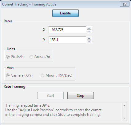
To enter the rate manually, you would select "Arcsec/hr" for units and
"RA/Dec" for axes, then enter the rates from the comet's ephemeris.
Comet rate training works like this:
First, center the comet in your imaging camera. If your imaging
application has some kind of reticle display, you should use that to
note the precise position of the comet on the imaging sensor. Once
this is ready, select a guide star in PHD2 and start guiding. Next
click "Start" in the Comet Tracking tool to begin training.
Take a continuous series of short exposures in your imaging camera
using your imaging application's Frame and Focus feature. Over time,
the comet will drift away from the starting location. Use PHD2's
"Adjust Lock Position" controls to move the comet back to the starting
location. You may have to experiment a bit to determine which way the
comet moves on the imaging camera sensor in response to the
Up/Down/Left/Right controls in PHD2. You may find it useful to enable
the "Always on top" button in the Adjust Lock Position window so the
controls stay visible on top of your imaging application.
PHD2 will quickly learn the comet tracking rate as you re-center the
comet. Once you are satisfied that PHD2 is tracking the comet, you can
click Stop to end the training. PHD2 will continue shifting the lock
position to track the comet until you disable comet tracking by
toggling the Enable button.
You can practice the comet training technique using the built-in
camera simulator. Check the "Comet" option in the Cam Dialog, and the
simulator will display a comet. Use a bookmark to mark the comet's
starting location, and use the Adjust Lock Position controls to move
the comet back to the bookmark location.
Managing Equipment Profiles
Equipment profiles were introduced in the section on Basic Use
where they are used as part of the 'Connect Equipment' dialog. If
you want to manage multiple profiles, you will probably want to use the
'Manage Profiles' button in the 'Connect Equipment' dialog. Using
the menu items there, you can create a new profile
or edit/rename/delete an existing one. Each profile holds
all the settings that were active at the time the profile was last
used. If you create a new profile, you can import these settings
from either the PHD2
generic defaults or from an existing profile. You can also use the
'Wizard' option to have PHD2 establish settings that are specific to
your equipment configuration. To
edit the settings in an existing profile, you first select it in the
equipment profile drop-down list, then click on 'Settings' under the
'Manage Profiles' pull-down. This will take you to the 'Brain'
dialog, where you can make whatever changes you want. Remember
than profiles are automatically updated anytime settings are changed
during a PHD2 session. Finally, you can import and export
profiles for purposes of debugging, backup, or even exchange with other
PHD2 users.
Advanced Settings for the Simulators
The device simulators were introduced in the Basic Use
section as useful tools for you to experiment with PHD2 and become
famliar with its features. Remember that you must choose
'Simulator' as the camera type and 'On-camera' as the mount type in
order to get the benefits of simulation. As you become more
interested in the details of the simulation, you can use the 'Cam
Dialog' button on the main display to adjust the simulation parameters:
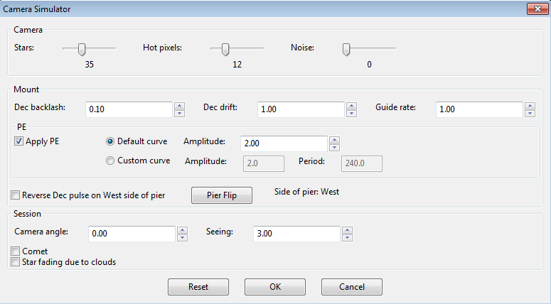
You can adjust simulated mount behaviors for declination backlash, drift
due to polar mis-alignment, and periodic error. You can also
adjust the 'seeing' level, which will create fairly realistic guide
star deflections that look like seeing effects. If you adjust
these parameters one-by-one, you'll see how they affect star
deflections and how the different guide algorithms react to those
movements. Of course, you're dealing with a "nearly perfect" mount in
these scenarios (except for backlash), so the simulation can't be entirely realistic.